Thin Films
![[url=https://pixabay.com/en/black-body-camera-canon-digital-2507/]"Camera"[/url] by PublicDomainPictures is in the [url=http://creativecommons.org/publicdomain/zero/1.0/]Public Domain, CC0[/url]
Camera lenses have optical coatings applied via vacuum deposition. Sometimes a single coating is applied, sometimes multiple coatings. These coatings are the reason the lens has the appearance of color to it.](https://www.geogebra.org/resource/Xxt34A5y/SBSjrA67jLhRV4gV/material-Xxt34A5y.png)
A thin film is often placed on the surface of lenses in order to minimize reflection of light off of the surface of the lens. The reason this is useful is that any light that reflects is obviously not transmitted through the lens. Minimizing reflection therefore maximizes transmitted light. In the case of photography being able to gather more light means faster shutter speeds and sharper images of anything in motion. There is a direct correspondence between cost of camera optics and light gathering ability.
In other optical products such as consumer eyewear, anti-reflective coatings are applied on the side of the glass facing the wearer to avoid seeing glare off the inside surface of glasses that can be annoying to the wearer.
In yet another example of thin films, metal surfaces are often anodized for mostly aesthetic reasons, although for aluminum the anodizing provides an anti-corrosive layer of protection. These anodized layers are colored, but not usually by use of pigments. It is often wave interference that gives the visual effect of color.
This same effect is often achieved by nature causing oxides to build up when polished metals get heated to high temperatures as in exhaust systems in cars or motorcycles or via other means.
In all of these cases, the physics involved is identical to the ceiling tile from the last section with two exceptions:
1. The wave number k to be used in the calculation needs to account for the fact that the wave that is traveling an extra distance through a thin film will have a reduced wavelength by a factor of the refractive index of the film, or , where the subscript zero indicates vacuum wavelength and the absence of the subscript is in the material. This makes .
2. A wave will sometimes be inverted upon reflection from a surface. Inverting a wave is equivalent to a phase shift. (Make sure this makes sense to you before moving on.) Given two waves, if only one of the two waves is inverted then we have another contributor to the relative phase between the waves besides just path length difference. We should in these cases think of the total phase difference between the two waves as arising from two sources, the reflective relative phase and the path-length-induced relative phase. It is the total that needs to be odd integer multiples of in order to have cancellation occur and even integers of for constructive interference. So we can write
The rule about when to expect a reflective phase change is simple: When a wave bounces off a material in which it propagates more slowly than the one from which it is coming, there will be a wave inversion, or a reflective phase change. If it bounces off a faster material, there will be no reflective phase change. This is true for all waves - light waves, sound waves, water waves, waves propagating on guitar strings, etc.
If we pause and reconsider our ceiling tiles for a moment, one thing we can be sure of is that both the front surface reflected wave and the back surface reflected wave will undergo the same reflective change as one another, if there is one. As it turns out, sound travels faster in solids (like tile) than it does in gases (like air). So bouncing off a faster material leads to no phase changes due to reflection. Take note, however, that if the two waves had bounced off of a slower material that both waves would have incurred a phase change so that , since is the phase difference of the two waves. So it would have changed nothing about our calculation. The cases that need our attention are those in which only one of the waves is shifted due to refelction while the other is not. Let's consider one of those cases now.
Optical Coatings
As mentioned above, cameras often have a lens coating intended to cancel reflected light so that the light gets transmitted to what used to be film and is now generally a CCD (charge coupled device). Such coatings are usually magnesium fluoride (MgFl), and are applied to the lens by evaporating the MgFl in a vacuum chamber. The vapor condenses slowly onto the lens during this process. The longer the lens is subject to the vapor, the thicker the layer will become. Such layers applied via vacuum deposition can be very precisely applied.
Cameras need to collect visible light of all wavelengths between roughly 400nm and 700nm. Putting a single anti-reflective coating on a lens, however, will only prevent reflection of a specific wavelength of light. In such single coating scenarios, the best choice would be to target the middle of the visible spectrum (550nm) so that light in the middle of the visible spectrum will not reflect at all and the light near the edges of the spectrum (red and violet) will only reflect a little bit. That "little bit" can be calculated, and you will learn how to do that later in this chapter.
So if the target wavelength is 550nm, there is one other thing we need to know: What are the refractive indices of the lens and the coating. We need to know both since their values will determine the reflective phase changes. Recall that bouncing off of a slower medium will flip the wave, or equivalently induce a reflective phase change of . Let's assume the refractive index of the thin film coating is 1.6 and that of the lens is 1.5. In that case, the wave reflecting off the film will be flipped and the wave off the lens will not be. Thus we get a . So without any path-length-induced phase difference the waves are already out of phase. While it might seem like we are done and don't need a path length difference, the problem with this is that without a path length difference there is no coating! So if we need to have some thickness of coating, we should aim to induce phase difference from the path length difference so that the total phase difference will be . That being established, the only thing left is to find the thickness of the film which I'll denote d. We know from before that , but we must be careful here to use the correct value for . The wave that travels the extra distance is not in vacuum, so its wavelength is shorter and thus wave number is higher. If I denote the vacuum wave number , then . So we complete the problem by solving for d. .
Index Matching
While the last example is a nice lesson in interference properties, it is not very realistic. The material usually used on camera lenses is magnesium fluoride (MgFl). The refractive index for MgFl is 1.34 at the middle of the visible spectrum. The refractive index for typical glass used in lenses ranges from 1.5-2. There is a way to calculate what fraction of light incident on a material will reflect off it. It is called reflectance or the reflection coefficient. The equation is more complicated if the incident light does not come in at zero angle of incidence, so we will assume it does. What we find is that the reflectance depends on the two indices of refraction of the materials involved by the following equation:
What this means is that when light reflects off a window of index 1.5, we should expect to be reflected, or 4% of the light intensity across all wavelengths. An interactive plot of the reflectance for a material n2 sitting in air n1=1.0 is shown below.
If there is a coating applied between the air and the glass that has a refractive index mid-way between the air's index and that of the glass, it will do the best job of transmitting the light. The reflection coefficient for coatings is just the same process twice. In other words, going from air n1 to a coating n2 to glass n3 will result in an overall reflectance of
The reflectance is minimized when the coating has an index exactly half way between the air and the glass. Thus, even apart from interference effects, the choice of coating material will always be made such that the coating falls roughly mid way between air and the glass on which the coating is deposited.
Reflectivity vs. Refractive Index For Materials In Air
Structural Color
The Morpho butterfly below has no blue pigment in its wings. The blue color is a product of interference much like that in thin films - except via a much more complex structure. While in the context of thin films on camera lenses the goal is to cancel reflection of light, in this case interference is set up to amplify reflection of one particular wavelength corresponding to that pretty blue color.
This structural color, as it's called, is present in many butterfly wings, bird feathers (phesant, peacock, blue jay) in beetle shells and in mother of pearl. What they all have in common - which helps to recognize structural color - is that the color changes with viewing angle. This tendency is called iridescence.
![[url=https://pixabay.com/en/blue-morpho-banana-flower-blue-1310711/]"Morpho Butterfly"[/url] by SHAWSHANK61 is in the [url=http://creativecommons.org/publicdomain/zero/1.0/]Public Domain, CC0[/url]](https://www.geogebra.org/resource/V45fzp4S/KimhQYHuqxyFhmpz/material-V45fzp4S.png)
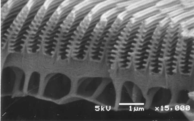
Morpho Wing Up Close
Looking at 15,000x zoom, one can see little tree-like structures on a Morpho butterfly wing surface. They are made of chitin, which is common among the insect and animal kingdom for making structures like exoskeletons. It is very similar in composition to cellulose in plant cell walls, and is clear in color. It is an animal kingdom counterpart to the keratin proteins that make up our nails and hair.
The refractive index of chitin ranges from 1.54 to 1.57. This is the material from which the "branches" on the trees in the image above are made. The gaps are air-filled. When light is incident from above, it strikes the top surface of a branch and reflects upward. Some light will have struck the next lower branch, and also the one below that, etc.
All the light striking the top surfaces must recombine constructively to make the blue color. If we assume the blue light is of wavelength 400nm, how far should it be between the branches? We need the phase difference to be for constructive interference. The path length difference is twice the distance between the branches, or While the light waves will be inverted upon reflection, that will be true of all the waves, so it will lead to no difference in phase between them. Putting all this together, we get , which leads to So we should expect the structures to be 200nm apart. This can be confirmed from the scale shown in the photo.